An Admonition: Embrace Imperfection
Enjoy this experience. Try to focus on your build’s successes more than its shortcomings. Our survey of surviving screen-used props revealed that no two are the same — or flawless. Each has its imperfections from rough eye cutouts to the liberal use of chrome tape. This made each original prop unique. Your replica will be too.
Part One: Preparation
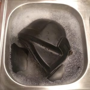
Step 1: Bath time
Use a mild dish soap and warm water to clean the helmet, eye slot, and mouth to remove residual mold release and other unwanted grime. Allow to dry thoroughly.
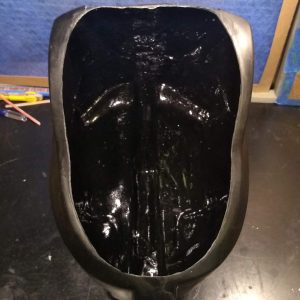
Step 2: First rough trim
Trim the helmet’s neck opening to make accessing the interior easier for later steps.
Step 3: First primer coat
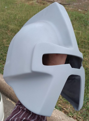
Prime helmet, eye slot, and mouth with sandable primer — preferably gray as that tint helps reveal areas that will require sanding and filling. Consider using Rust-Oleum 2-in-1 Filler & Sandable Primer for this initial coat.
Step 4: More rough trims
Using a rotary tool, cut openings for the eye slot and mouth — make certain to stop within 2 to 4 mm of opening boundaries revealed in the helmet casting.

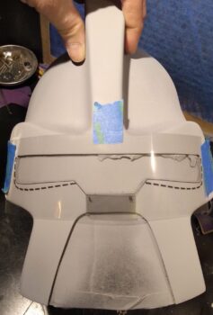
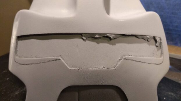
Step 5: Revise eye slot
Using the supplied transparency template, mark extended cuts that slightly widen and extend the bottom curves of the eye slot.
Step 6: Fine trims
Take this process slow and use hand tools.
Surface: Sand opening edges until you achieve reasonably crisp lines. Metal files work well, but so do simple tools: coarse sandpaper glued to a paint stick forms a maneuverable sanding block and another piece of sandpaper wrapped around a pencil is ideal for gentle curves.
Interior: Note the adhesion areas necessary to mount eye slot and mouth to the helmet. Reduce the thickness of the helmet casting in the corresponding areas of the helmet interior.
Neck opening: Refine rough cut made in Step 2.


Step 7: Fill edge voids
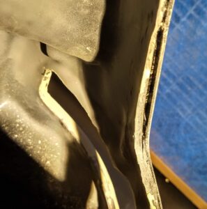
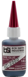
Use mixture of resin shavings and CA glue to fill any voids along the freshly trimmed openings. You may also consider using Bob Smith Industries’ IC-2000 Tire Glue. It’s a flexible carbon and rubber filler that bonds with the strength of Super Glue, yet still sands smooth.
Step 8: Fill. Sand. Prime. Repeat.
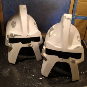
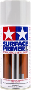
Study your parts and determine areas that require further sanding and/or filling with Bondo or modeling putty. Check your work with additional primer coats until each part obtains your desired level of smoothness. Switch to a finer quality rattle-can spray such as Tamiya Surface Primer (Gray) for these revision coats.
Pay particular attention to the smoothness of what will be the silver/chrome areas of the helmet as they are the least forgiving.
Step 9: Step Back
You’ve done a lot of fiddly stuff in Steps 1-8. Take a break. Let the primer and fillers dry overnight.
Step 10: Final inspection
You may find yourself wanting to return to Step 8. Don’t.
If you must, take a super fine grit sanding sponge and gently brush away any debris on your primed surfaces. Feel for any snags along the surfaces with your (clean) bare hands.
Marvel at your work thus far!
Part 2: Electronics
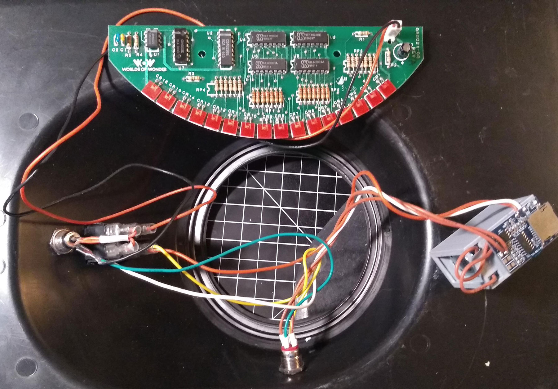
There are likely better ways to assemble these components. In the interest of accessibility, we’ve tried to make the process simple and open to modification. Everything runs on a generally safe 5-volt circuit. First, a quick reminder:
Wiring Guide

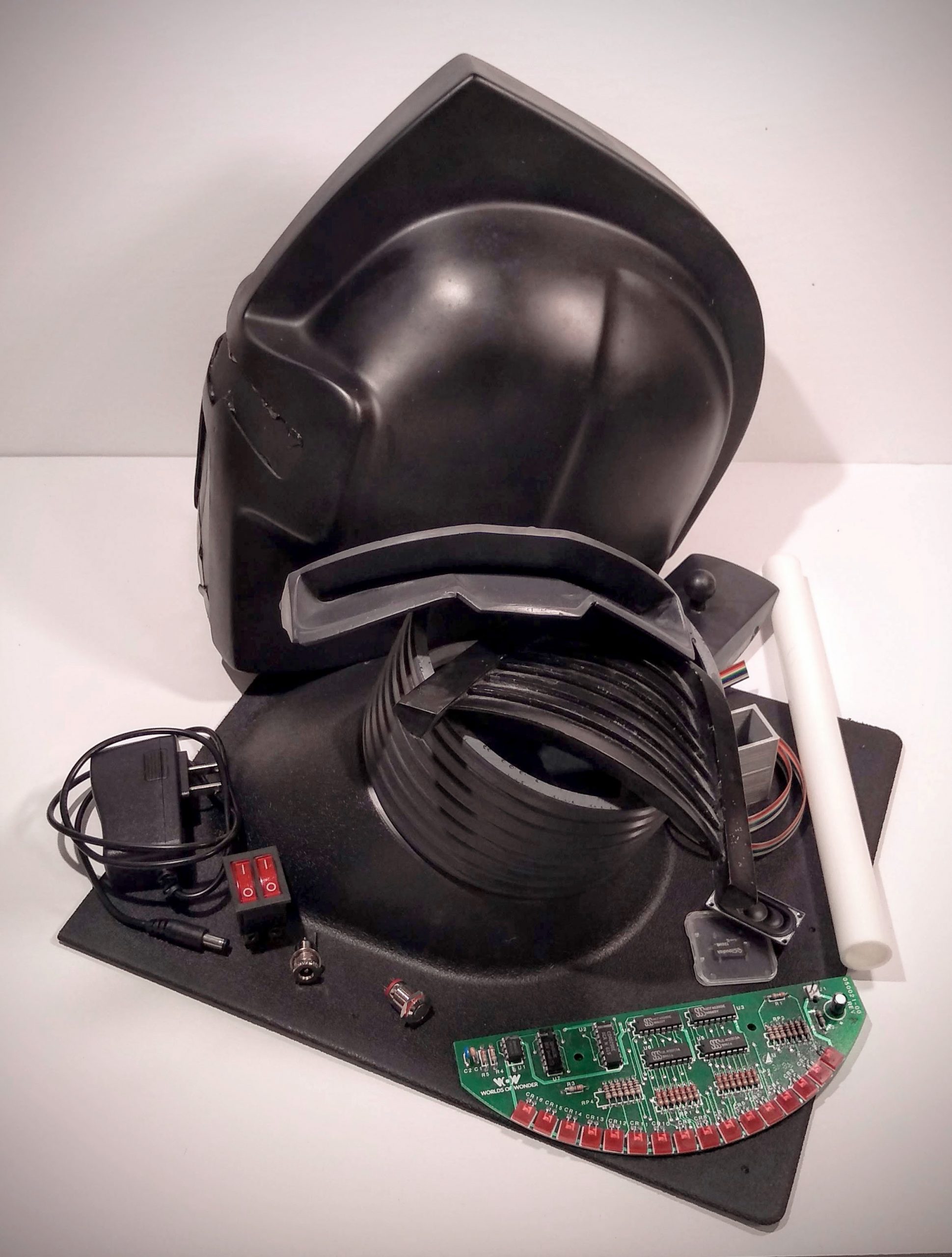
Components
- 5V Power Supply
- Power Socket
- Dual Rocker Switch (Eye / Audio)
- WOW Board (Vintage Worlds of Wonder scanning eye)
- MP3 Player
- Micro SD card (MP3 audio files)
- LED Button (Advances audio clips)
- Speaker
- Speaker housing
- 42” red wire (3” x 2; 12”, 24”)
- 22” brown wire (8” x 2; 3” x 2)
- 24” black wire
- 12” white wire
- 8” yellow wire
- 8” green wire
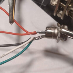
Power Socket
Step 1: Connect two positive wires to center post (3″ red x 2). Connect three negative wires to outer tab (24″ black, 12″ white, 8″ green).
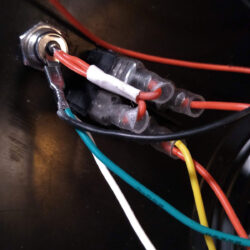
Dual Rocker Switch
Step 2: One side powers the scanning eye while the other powers the sound FX. Connect one of the 3″ red wires to each switch from the power socket. Attach the 24″ red wire to the scanning eye side. On the opposite, attach the 8″ yellow wire and 12″ red wire.
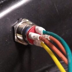
LED Button
Step 3: Two poles power the red LED while the other two activate the momentary switch. Connect the 8″ green wire to the negative LED tab and the 8″ yellow wire to the positive. Connect the two 8″ brown wires to the remaining posts.
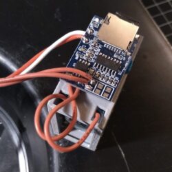
MP3 Player & Speaker
Step 4: Connect the 12″ red wire from the Rocker Switch to power the MP3 board. Route the 12″ negative white wire from the Power Socket to the GND (Ground). Connect the two 8″ brown wires from the LED Button to the first two switch positions. Connect two 3″ brown wires from MP3 board to speaker.
WOW Board
Step 5: Connect the 24″ negative black wire to the right terminal of the bi-pin. Connect the 24″ positive red wire to the left terminal.
